Hey everybody! Let’s EXPLORE Autodesk Fusion 360!
If you’re anything like me, then you always have to try out gadgets. Especially gadgets that fly. As I work my way towards a higher level of quadcopter piloting, I leave a trail of crashed and burnt-out drones (hey, they are called “hobby grade” drones for a reason). Since I have an abundance of damaged drones, I decided to use one for this week’s Fusion Explore blog.
My goal was to design and print a replacement chassis, making it small and light enough for the tired motors to handle. Seemed easy and somewhat useful to me. Let’s see how it went…
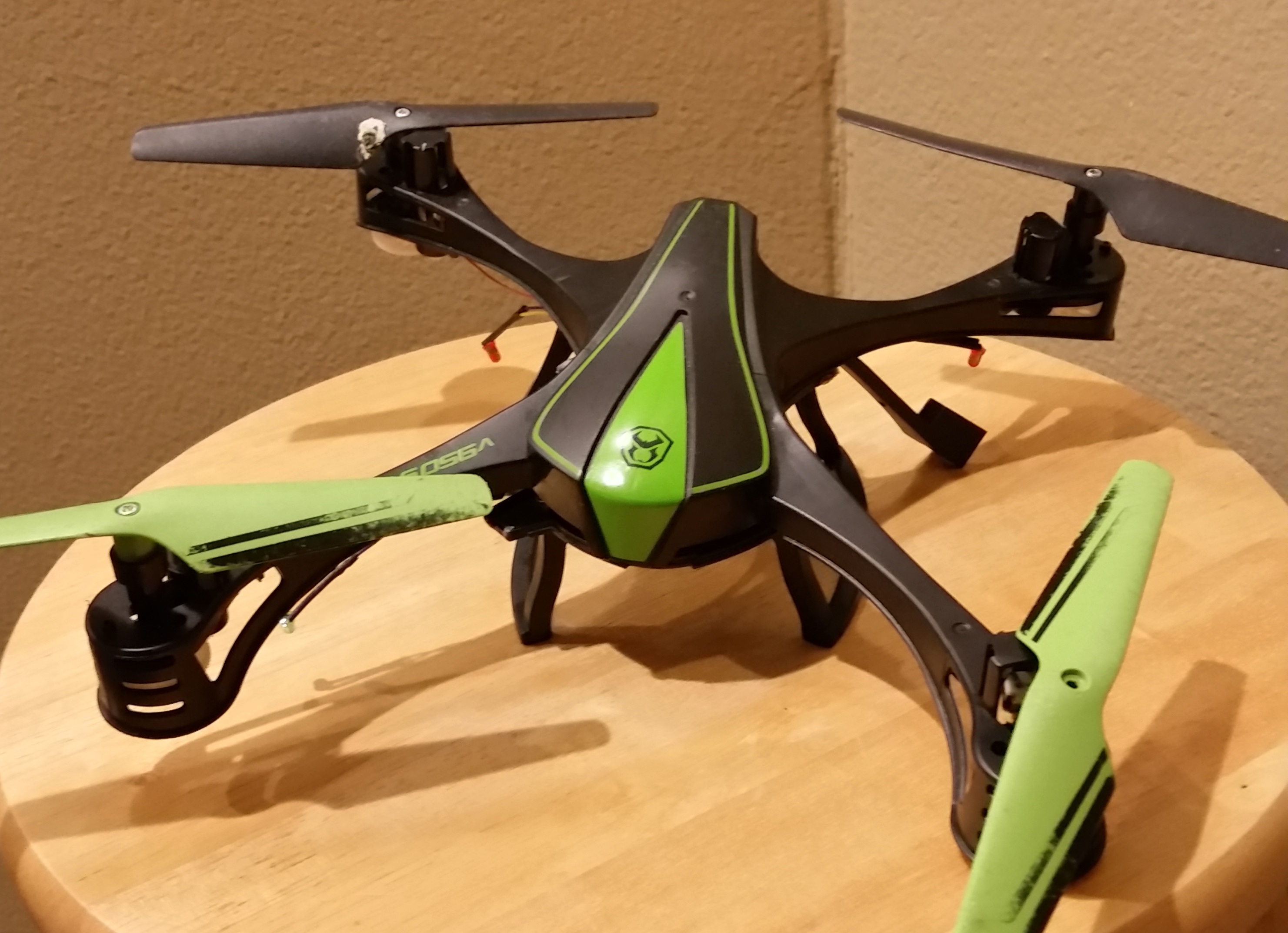
I have an abundance of damaged drones

Add Fusion 360 to
your cart to
subscribe now
Okay, first I took the dimensions of the quadcopter, figuring out the basic size footprints of the components. I decided to reduce the overall size by bringing the motor spacing down to a 150mm by 150mm.
Next, I had to determine what to preserve from the original quadcopter. Along with the electronics, the only plastics part to be preserved were the motor/propeller assemblies. Basically, each of these little assemblies contains a motor and a mechanism for reducing the rotational speed of the propellers. While I could have modeled this part as well, I decided to leave “good enough” alone and reuse it.
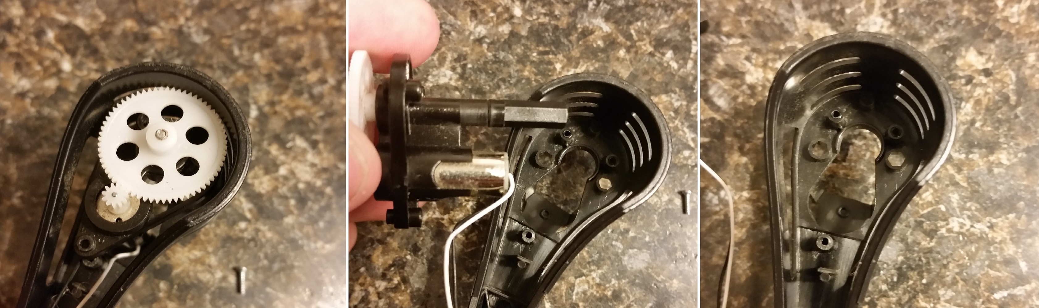
I had to determine what to preserve
My first design step was to design a mount for the motor assemblies, so that I could securely mount them using fasteners from the original chassis. So, using my trusty digital calipers, I measured the basic footprint of the motor assemblies and measured out the placement of the fastener posts. I was careful to replicate all features (from the original frame) that were necessary to mount motor assembly, allowing for plenty of clearance where the drive shaft pushes through the chassis.
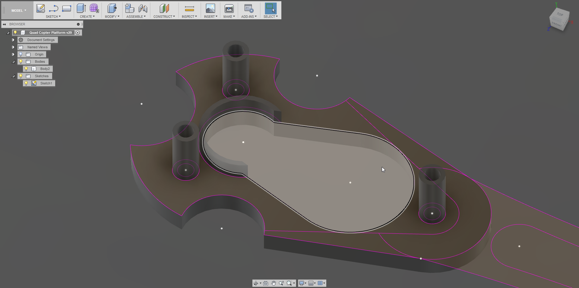
I was careful to replicate all necessary features
There are several takeaways from the sketch/modeling process: ALWAYS fully constrain your sketches, try to only create ONE body/component per sketch, and follow Rule#1 (create new components BEFORE you start a sketch for a new part, so that you start a unique timeline for that part).
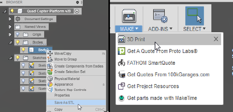
choose “Export STL”, or click the “3D Print” button
Anyways, once the motor mount prototype had been modeled, I needed to make sure that would work in the real work. So, I exported the part as an STL (right click on the body/component under the browser menu and choose “Export STL”, or click the “3D Print” button on the ribbon menu). Then I uploaded the STL to Eiger (proprietary MarkForged slicer/translator) and sent it to the MarkForged X7. Once it had printed, I tested the fit and made adjustment to the model accordingly. It took about four iterations to get everything just right, both in fit and in durability (I was still getting used to the tolerances and capabilities of this printer).
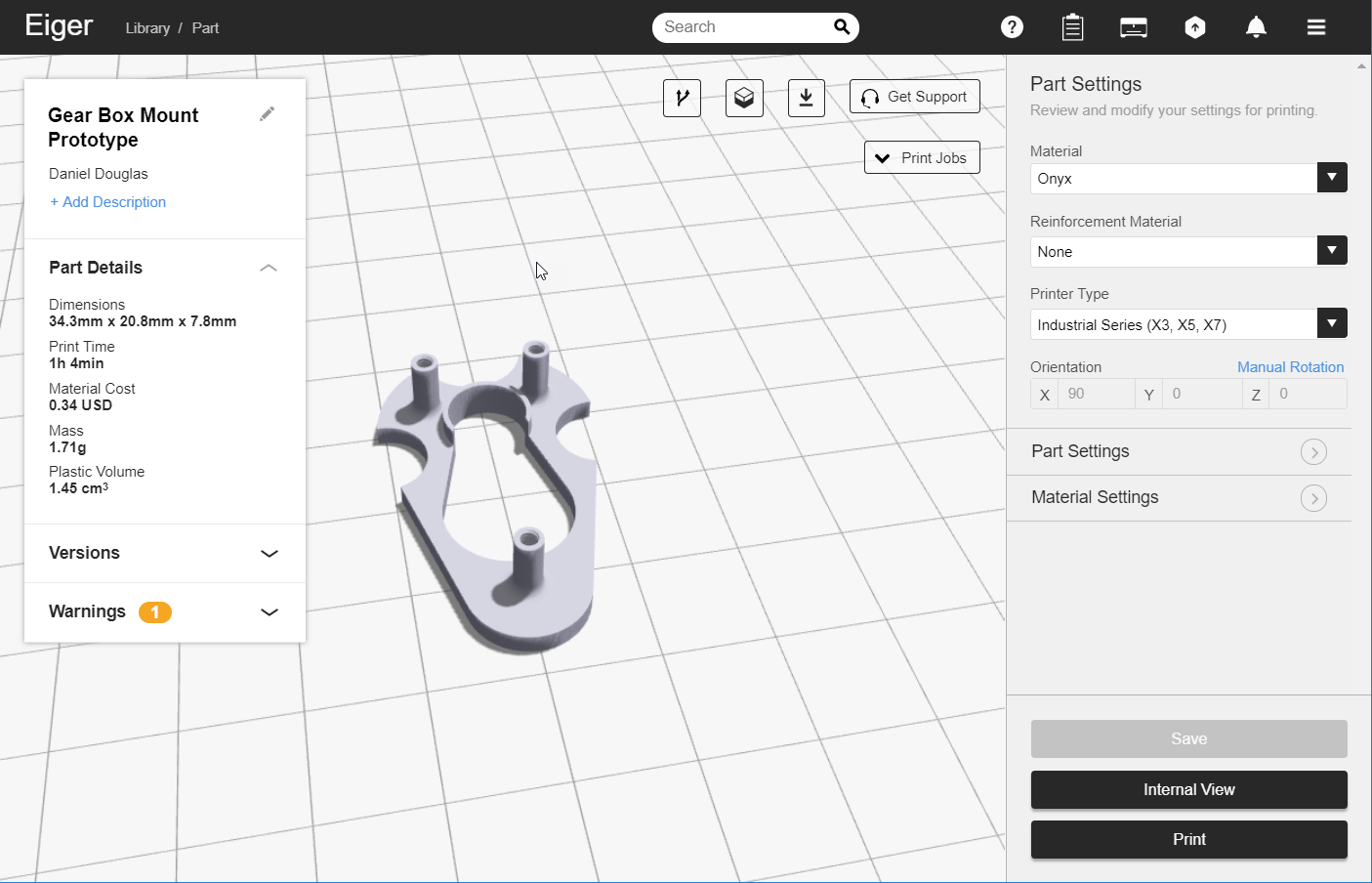
I uploaded the STL to Eiger (proprietary MarkForged slicer/translator) and sent it to the MarkForged X7
That is all for “Part 1”! Stay tuned for more!
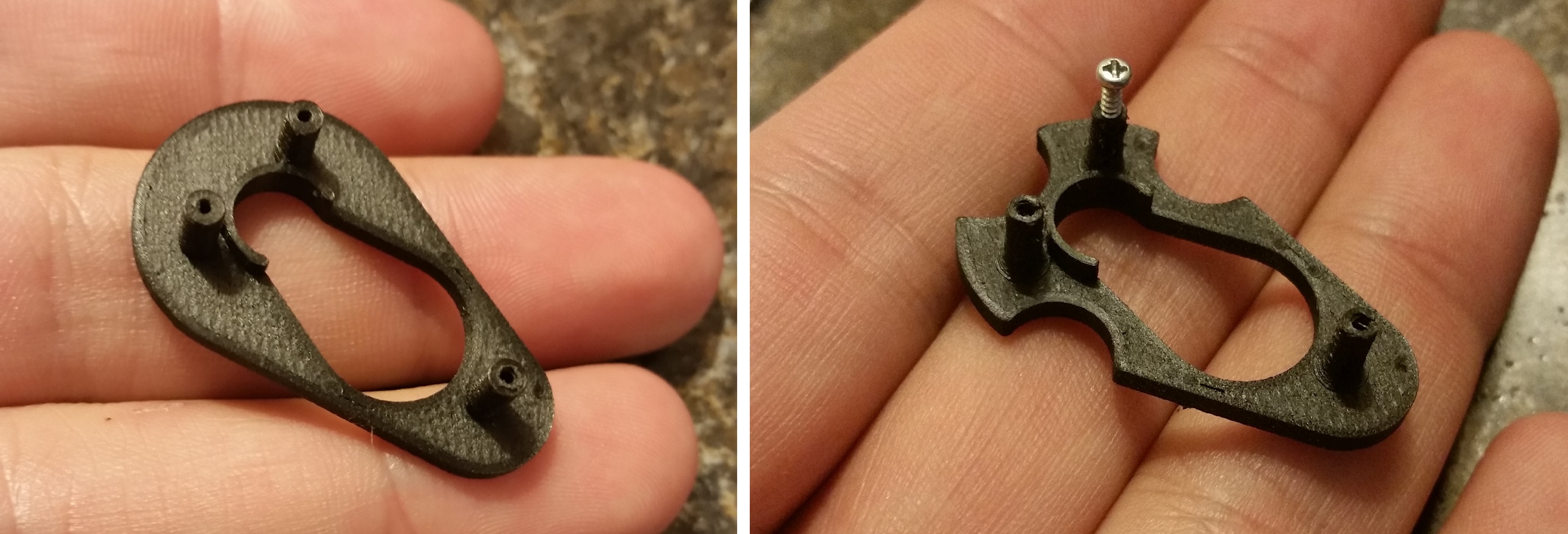
It took about four iterations to get everything just right, both in fit and in durability
*My colleague Ryan recommended that I break the blog into parts, so that I could go into more detail. Great idea, RyJo!