Published by 3D Systems, 2017
Editor’s Note: This guest post is written by Charlie Garcia, an MIT AeroAstro undergraduate student. Kelly Mathesius helped operate the tests for the plastic rocket and is a senior and rising graduate student in the AeroAstro department. Matt Vernacchia is the plastic rocket project lead, a graduate student in AeroAstro. All three are members of MIT Rocket Team, a student engineering group dedicated to flying high powered experimental sounding rockets. They are all certified members of the National Association of Rocketry with dozens of rocket launches under their belts.
Background:
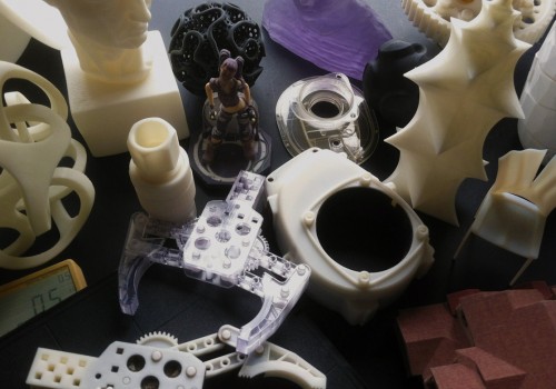
Rocket motors commonly consist oflong, sleek, metal tubes surrounding dark rubbery propellant - this design is commonplace in rocket motors, and for good reason. The solid rocket fuel inside these motors can burn at over 5,000 degrees Fahrenheit and generate pressures of over 1,400 pounds per square inch. It’s quite possibly the last place you’d expect to find a plastic part. That sounded like an interesting challenge, so two students and myself picked it up and ran with it. As a result of this project, we created the first rocket motor 3D printed from plastic. Many groups, such as Space X and NASA, have printed rocket motors from metal, but metal printers carry a six or seven figure price tag. Our motor is the first to be made on an accessible, high strength 3D printer: the Markforged Mark Two.
Ask How You Can Own a 3D Printer Today:
Design and Material Selection:
“SLS 3D printing enables us to design for superior strength and durability,” says Jon Christensen, marketing and sales manager at Idaho Steel. “For those new to it, the idea of ‘printing’ parts may not convey the fact that when finished, these parts are solid plastic. Parts can also be designed for added strength in ways that are not possible through traditional machining.”
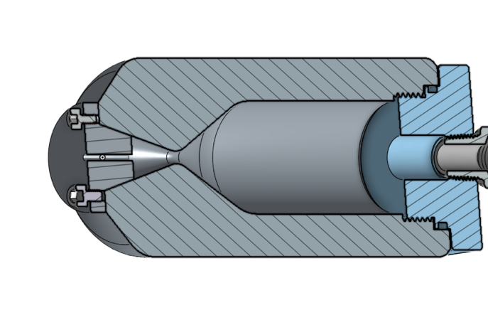
A cross section of the 3D printed rocket motor in CAD.
The CFF (Continuous Fiber Fabrication) technology Markforged provides enables a plastic part to withstand the extreme environment of a rocket motor. Fiber infill enables the material to withstand both pressure and thermal loads. The internal pressure creates two directions of mechanical load in the motor case: a hoop stress (circumferential) and an axial stress. The Mark Two enables us to support the hoop stress by laying hoops of continuous fiberglass around the inner circumference of the motor case. The fiberglass increases the tensile strength in the circumferential direction by an order of magnitude compared to nylon alone, and Onyx helps support the axial stress on the motor case. The nylon-chopped carbon mixture offers improved strength and layer adhesion over other filament deposition plastics.
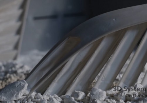
Fiber infill also enables the material to withstand the thermal loads of the rocket exhaust. Like most solid rocket nozzles, our nozzle is ablatively cooled. This means that as the material is heated part of the material 'boils' away. This process carries away heat, helping the remaining material to stay cool. Because part of the material is sacrificed to cool itself, ablative materials get used up and have a limited lifetime. With good engineering, we can make the lifetime long enough to survive a few firings of the motor. Ablative materials are typically a mixture of glass or carbon fibers with a plastic (usually phenolic resin). The nozzles of the Space Shuttle Solid Rocket Booster and the reentry heat shield of SpaceX's Dragon are both protected from heat by fiber/phenolic ablatives. As the material heats up, the phenolic resin slowly 'boils' away. The fibers can resist much higher temperatures (2000-3000 degrees Celsius), and remain behind as a porous char. The char layer at the surface insulates the material behind it. This char insulation beneficially slows the rate of ablation.
Markforged's fiberglass/Onyx material is a decent approximation of fiber/phenolic ablative. The inclusion of fibers is essential. If we tried to make our nozzle out of PLA or ABS on a traditional filament-deposition printer, there would be nothing to form the insulating char layer. Without the fibrous char layer, the nozzle would be destroyed by heat and erosion. Nylon gasifies at a somewhat lower temperature than phenolic, and the fiber loading is somewhat less that typical ablatives. However, the printing materials have a huge manufacturing advantage. Traditional ablative nozzles require investing a lot of capital in specialized mandrels and filament winding machines. Design changes are expensive and incur a long lead time. By contrast, with fiberglass and Onyx we can print our nozzles on a relatively low-cost, multi-purpose machine and can create a new nozzle in days.
Production:
We used Markforged’s Eiger slicer to lay out the infill and set up the fiber routing required for our design. The full prints ended up taking two days and seven hours to finish printing, much quicker than the several weeks lead time manufacturing a motor case and nozzle via traditional methods takes. Even better, it doesn’t require any tooling changes. Two hours in the machine shop finished the parts necessary to hold the motor to the test stand, and with a few O-rings, some grease, pressure measurement equipment, and some sheet aluminum completed we were ready to assemble and test.
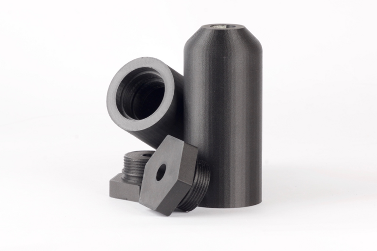
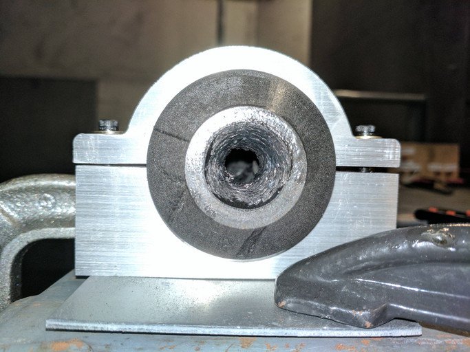
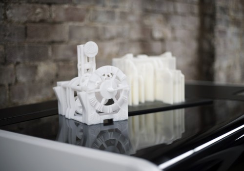
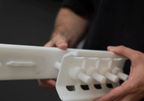
Two prints of the rocket motors, printed with Onyx and fiberglass reinforcement.
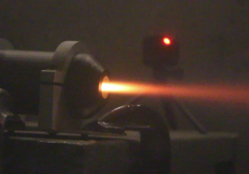
The assembly of the plastic rocket is quick and easy: apply grease, slide in place, screw on the end cap hand tight. An electronic match gets threaded up the nozzle to light the whole assembly. A cap seals the nozzle closed until the motor lights, helping the motor pressurize and light correctly. The blast chamber door closed. The three of us work through a brief checklist, one we’ve worked through many times before. A countdown echoes off the concreate walls. “3, 2, 1, Ignition!” A pop. A rising hiss as the chamber pressurizes. A low rumble as the motor finally catches and burns for five seconds before sputtering to a stop. The acrid smell of hydrochloric acid hangs in the air as the ventilation fan sucks the smoke out of the blast chamber. Sitting there in the hazy view on the cameras is an intact plastic rocket case.
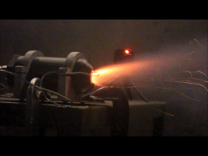
The first test with the 3D printed rocket motor.
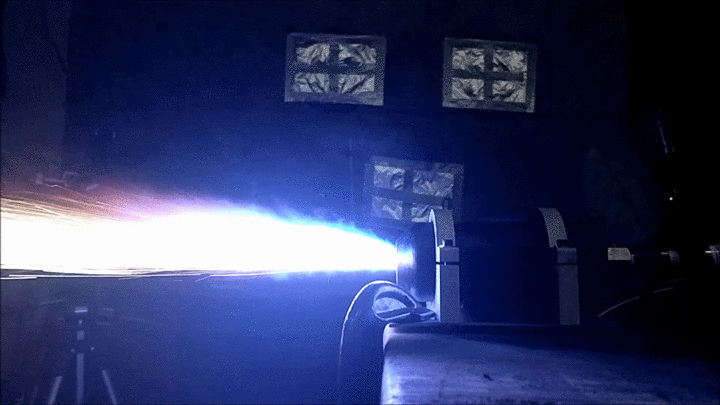
A second of the same rocket motor.
We were quite ecstatic. It’s always a thrill to take a material and use it beyond its physical limits through clever engineering. It is not immediately obvious if a commercial application exists for plastic rocket motors: for now they are heavier and lower performing than commercially available alternatives. However, we’re so excited by the first test that we’re already following up with better designs and more experiments.
The burnt out fiberglass-Onyx rocket motor.
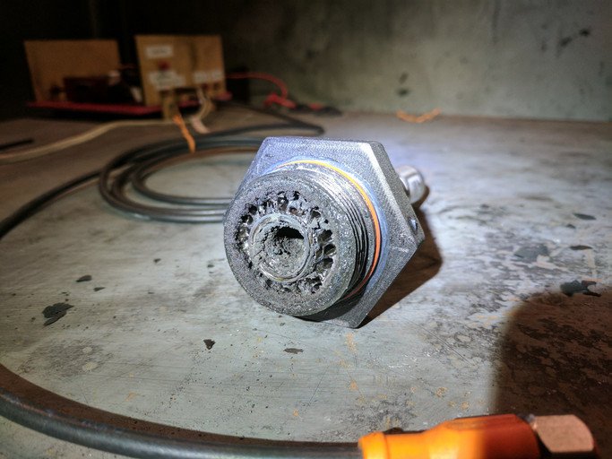
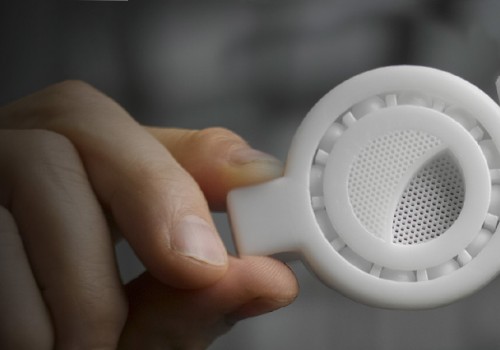
A post-test rocket motor cap.
Data:
This test shows promise, but it’s a long way from being useful. This graph shows the pressure in the chamber of the motor. The erosion of the throat is very obvious. You can watch the pressure drop as the burn progresses. At peak pressure, we were at barely 3.5 atmospheres of pressure. That’s hardly a torture test. Over the coming weeks we have tests planned up to 5 MPa, or 725 psi.
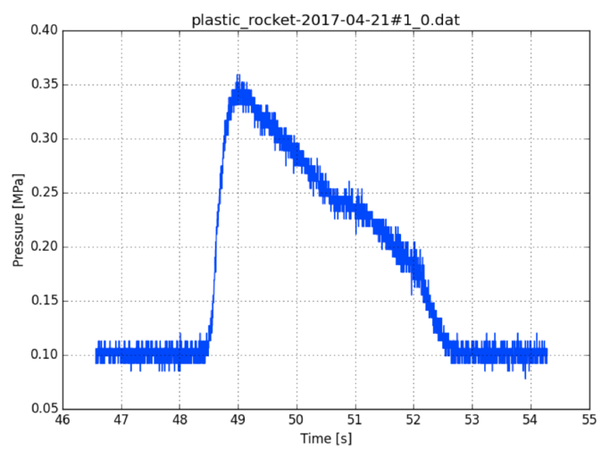
Data collected from the initial rocket motor test.
This will require additional design work, more rocket fuel, some extra cameras to capture the event, and, of course, lots of 3D printing. We are grateful to Markforged for their excellent collaboration on this project, and to the MIT Department of Aeronautics and Astronautics for the use of their rocket test facilities.
You can read the MIT Rocket Team's original post here.
Additional Resources

Success Stories
Featured Products
Featured Products
Success Stories

Featured Products
Success Stories
Success Stories
Featured Products

Success Stories
Success Stories
Featured Products
Success Stories