Welcome back everybody! Let’s EXPLORE Autodesk Fusion 360!
This post is part of an ongoing series, so if you want to start at the beginning, then click here.
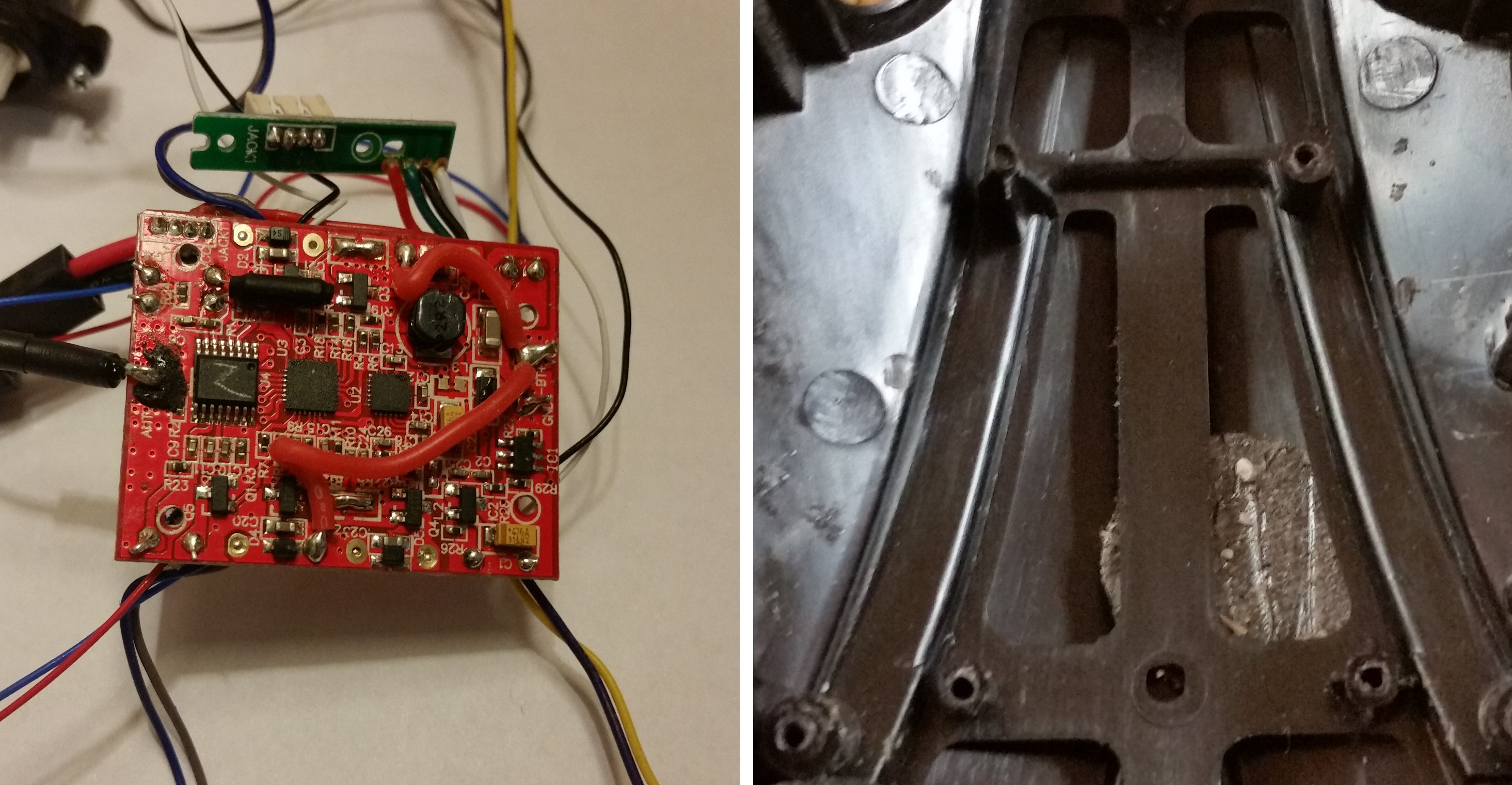
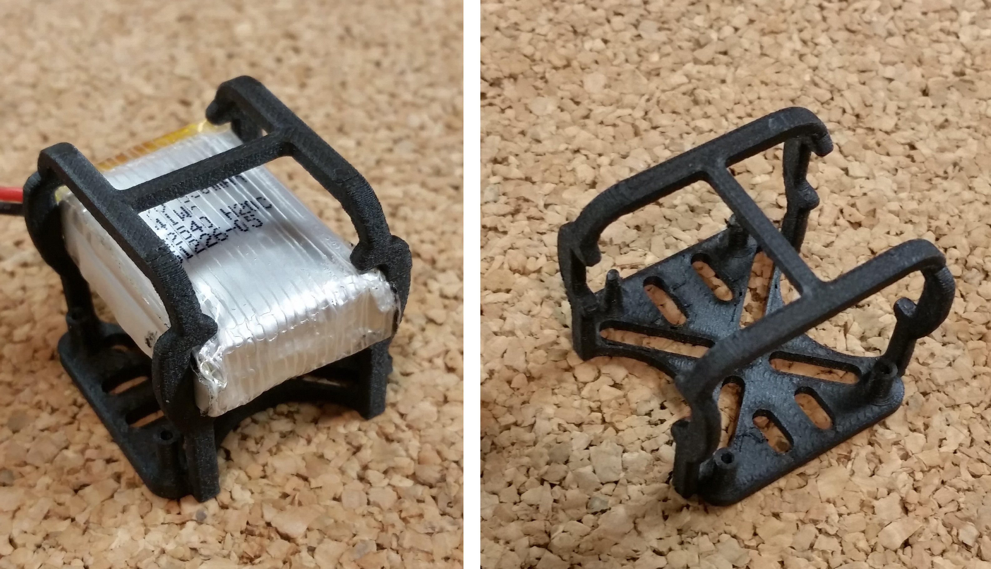
After designing and prototyping the motor mounts, I had to figure out what to do with the control board and battery. In order to achieve a lightweight and minimalist design, I decided to simply mount the control board directly to the airframe and build a sort of crash cage around it. Since all of the quadcopter electronics are soldered together (and I didn’t want to tear everything apart and solder it back together), the crash cage would need to be wide enough for the motor assemblies to fit through. Additionally, I still needed a place for the battery pack, which was the heaviest single component.
I had to figure out what to do with the control board and battery
First, I sketched a layout of the frame, placing the motor assembly mounts 150 mm apart (so that the propellers would have plenty of clearance). Once I had extruded the layout profile, I started a new sketch on the top face of the frame.
Second, after sketching and centering the basic outline of the control board (making the footprint slightly larger than the board), I placed and dimensioned the fastener posts. Then I extruded the base of the cage -- not the whole frame -- and the fastener posts, and double-checked the size of all of my real components. Since the board was ~27mm wide, I only had to offset the cage struts by 2mm from each side of the board.
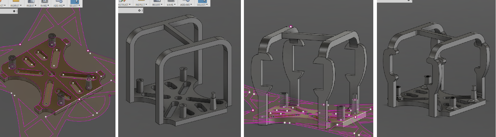
Here are a few screenshots
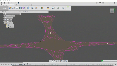
Third, I started the surprisingly difficult process of building the cage. The required techniques were actually quite simple, but because I was trying to make a healthy parametric model -- for quick redimensioning -- I had to keep redoing my order of operations (otherwise a quick adjustment would cause all downstream features to explode). Since I was trying to produce a single flight-frame, I was working out of a single component and had to deal with the messiness of a single command timeline. Here are a few screenshots to show a few of the operations that I decided to use.
Fourth, I printed the cage on the MarkForged X7, so that I could verify that it fit the battery and control board. I also tested the cage to see if it could withstand crashes (hit it and crushed it until it broke). The Onyx material, a proprietary MarkForged filament, is essentially nylon and carbon microfibers. I found it to be lightweight, flexible, very self-adhesive, and providing an attractive matte-black finish. Basically, it was the perfect material for my project objectives (durable, light airframe). All in all, I printed four iterations of the cage.
All in all, I printed four iterations
If you want to learn more about this project, then stay tuned for the next installation in this series. As always, thanks for reading and feel free to reach out in the comments!